I worked with the MIT CSAIL Distributed Robotics Lab run by Daniella Rus under the supervision of Lillian Chin as an undergraduate researcher on a project designing and fabricating dual-flipping robotic mechanisms. For this project I built off of the work done by previous undergraduate researchers and Dr. Chin herself.
This project was inspired by the Hoberman Switch Pitch toy that is able to invert from one geometry to another. The goal of this project was to redesign the core inverting mechanism to be self-inverting by incorporating some kind of internal electromechanical actuation.
redesigning the transmission for ease of assembly
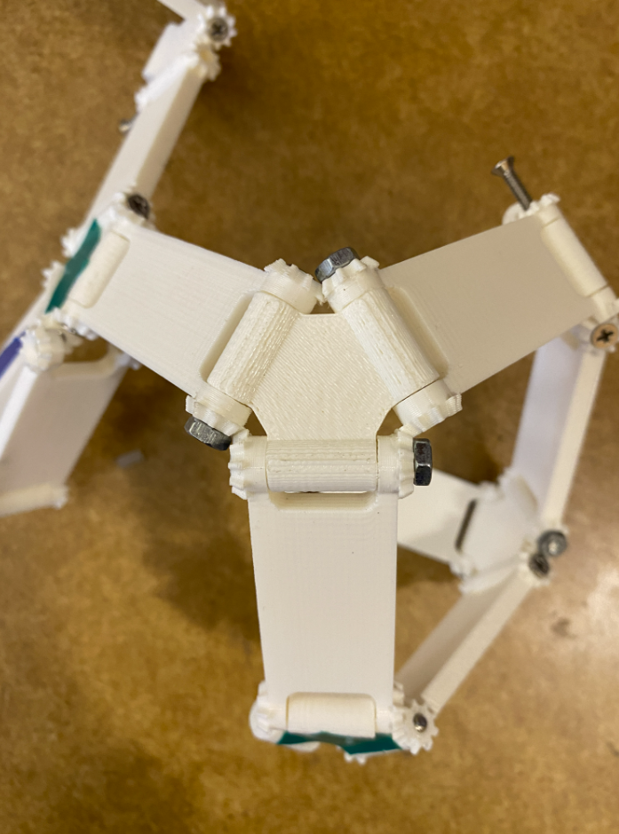
When I first started the project it was essentially at this stage with small 3D printed gears held onto each joint with bolts. There were a number of problems: the bolts made it difficult to assemble, the plastic gears often broke, the 3D printer could not print small details well (gears didn't mesh perfectly), and the struts did not all move in sync.
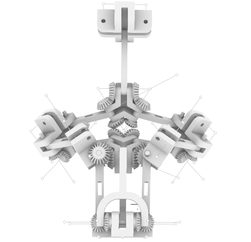
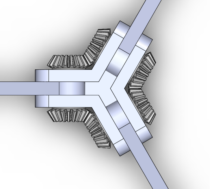
My first goal was to redevelop the mechanism to work with off-the-shelf gears that could stand up better to the high loads the transmission required. The mechanism requires triangular and pentagonal joints in order to properly invert. I figured out that in order for the struts to line up, the gears on every other strut needed to have a slightly offset rotational position compared to the others.
This new design did not involve bolts to hold the gears on, but instead a custom machined semi-circle that fits onto a semi-circular rod. This design connects the rotation of the struts to the rotation of the gears without the possibility for them to become disconnected. The strange geometry of the bevel gears together makes them difficult to take off, so for this stage of the design, I did not incorporate a more robust method for securing them to the rods.
3D printed prototype of new gears
(image coming soon)
inverting from one geometry to another

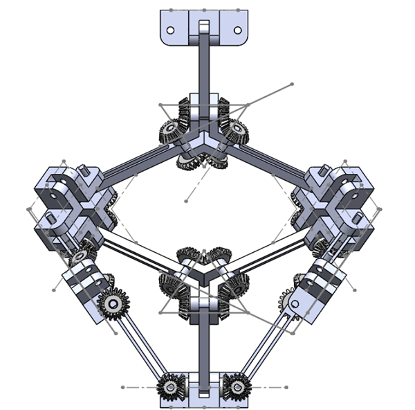
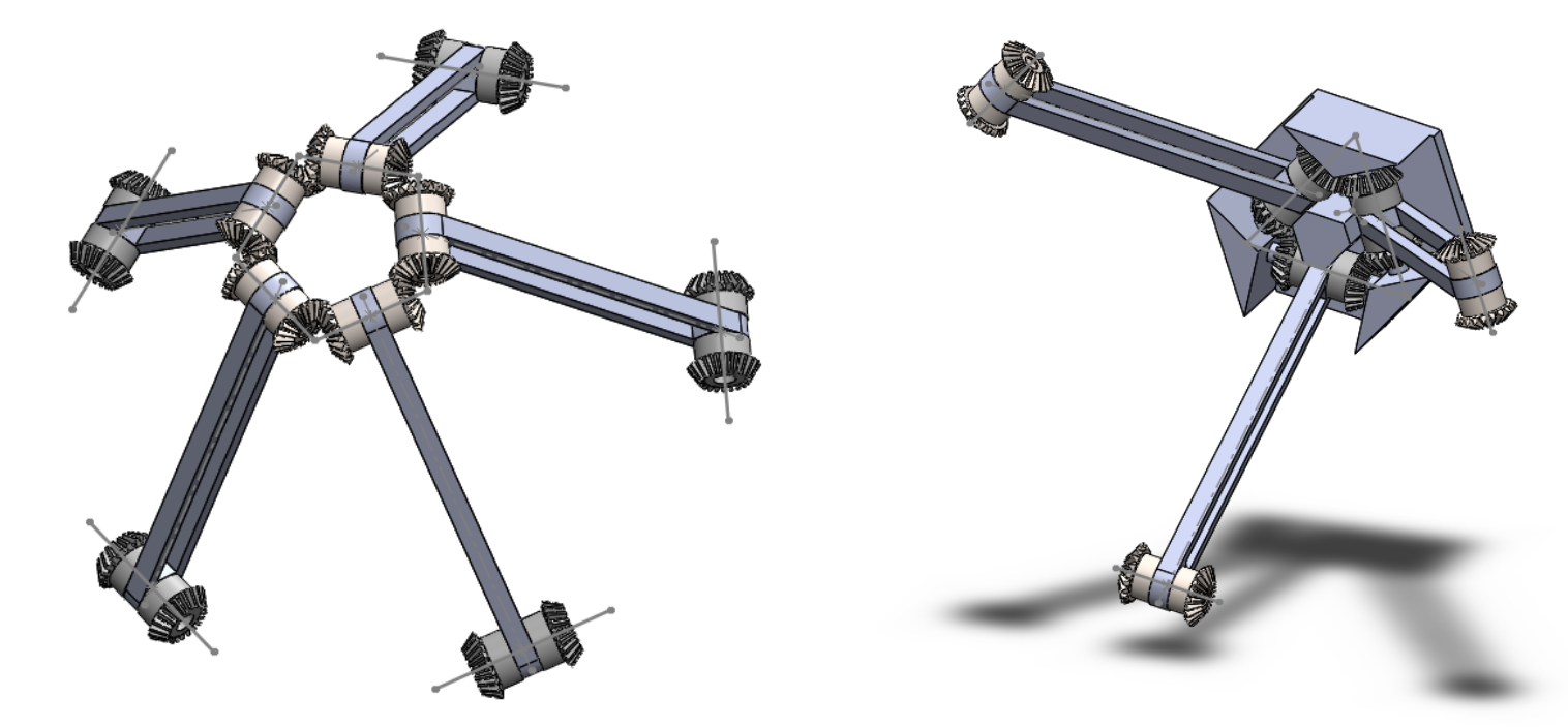
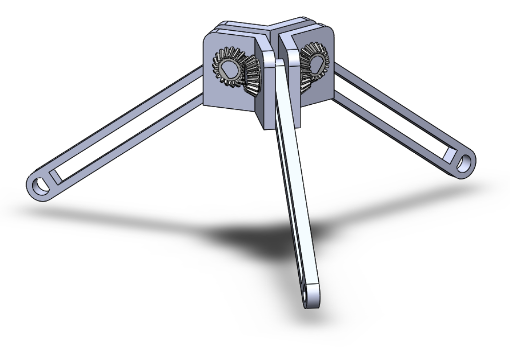
At this point in the project I shifted to an inverting geometry that involved triangular and quadrilateral nodes rather than pentagonal because of the dramatically increased simplicity of finding 90 degree bevel gears rather than __ degrees. I designed a similar hub for the square node and collected the two in one assembly that created one half of the geometry. I discovered that the strut length did not matter to the geometry as long as they were all equal, so it was only a matter of create the right moment.
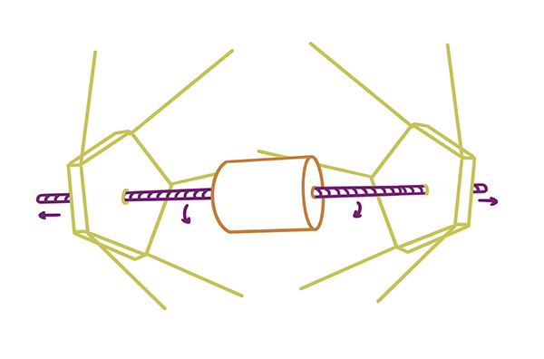
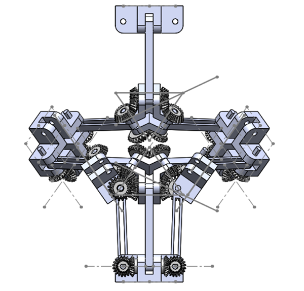
actuating the mechanism with one source
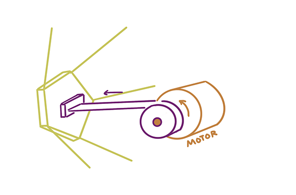
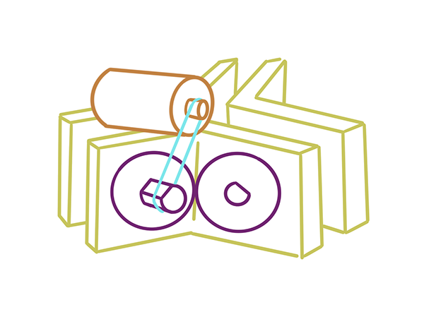
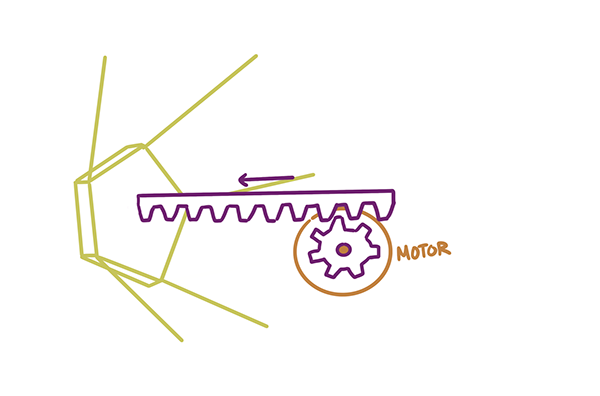
When it came to actuating the mechanism I looked at a number of ways I could use rotational or linear motion to either rotate the gears in one "driving" node or push the geometry out and in to accomplish the inverting motion.
While I had plans to attempt both a linear and rotational design, I prioritized the rotational method for my first prototypes because they seemed the most likely to succeed.